Wiring
Best Model Railroad Wire and Terminals
Quick answer
The best feeder and accessory wire for most layouts is the BNTECHGO 22 AWG Silicone Wire Red and Black 250 ft Stranded Tinned Copper at $46.98, because the paired red and black colors keep polarity consistent across dozens of feeder drops, while the heavier bus itself needs a thicker gauge sized to its own length.
Layout wiring splits into two very different jobs that get confused constantly: the bus, a pair of heavier wires that runs the length of the layout carrying the full current load, and the feeders, short thin drops from the bus up to each rail joint. The BNTECHGO 22 AWG Silicone Wire Red and Black 250 ft Stranded Tinned Copper is right-sized for feeders and general accessory wiring; the bus itself needs a heavier gauge than the catalog carries, sized using our bus wire gauge calculator.
For the actual technique of connecting a feeder to rail, see how to solder rail feeders and how to wire a DCC layout.
On this page
- What gauge wire do I need for a bus, and why is it not the same as feeder wire?
- Wire and terminal hardware compared
- How do I connect a feeder to the bus without soldering every single joint?
- How do I know if my bus wire is actually too thin?
- Beginner: feeder wire for a first layout's worth of drops
- Intermediate: a terminal strip to organize a growing bus without soldering every joint
- Expert: extension wire for a control panel with many remote turnouts
What gauge wire do I need for a bus, and why is it not the same as feeder wire?
A layout's electrical bus runs power out to the far end of the layout and the return path runs back, so a 25 foot bus run is actually 50 feet of copper carrying current, out and back. That effective length, not the straight-line distance across the benchwork, is what determines how much voltage the bus loses along its length and therefore how heavy a gauge it needs. Our bus wire gauge calculator takes your actual run length and expected current draw and returns the minimum gauge for your own layout; heavier bus wire in the 12 to 14 AWG range, such as 12 AWG stranded copper wire, is typically what that works out to for a mid-size layout.
Feeders are a different story. Each one only carries the current for its own short section of rail over a run of a few inches to a couple of feet, so a much thinner wire like the BNTECHGO 22 AWG Silicone Wire Red and Black 250 ft Stranded Tinned Copper is entirely adequate, and its flexibility makes it easier to route and solder than a heavier gauge would be.
Wire and terminal hardware compared
The bus itself is a hardware-store item at the gauge your own layout calls for; the catalog covers the feeder wire and the terminal hardware that connects everything to it.
Feeder wire can be much thinner than the bus it connects to, since each feeder only carries current for its own short section of rail.
| Item | Use | Price |
|---|---|---|
| BNTECHGO 22 AWG Silicone Wire Red and Black 250 ft Stranded Tinned Copper | Feeders and accessory wiring, paired colors for polarity | $46.98 |
| BNTECHGO 22 Gauge Silicone Wire Spool 250 ft Brown Stranded Tinned Copper | Single-color feeder or accessory runs | $25.98 |
| Terminal Block 8 Circuits 600V 15A Dual Row Screw Terminal Strip 6 Sets | Screw-terminal distribution from bus to feeders | $13.89 |
| Bachmann 10 foot Remote Switch Extension Wire | 10 foot extension for remote turnout motor leads | $17.46 |
| 12 AWG stranded bus wire | The bus itself, sized to your run with the calculator above | Varies |
How do I connect a feeder to the bus without soldering every single joint?
A screw-terminal strip like the Terminal Block 8 Circuits 600V 15A Dual Row Screw Terminal Strip 6 Sets lets you land a bus wire on one side and multiple feeder drops on the other without a solder joint at the distribution point itself, which is useful for a bus that may need to be reconfigured later. The rail-to-feeder connection is still best made by soldering, covered in our guide on how to solder rail feeders, since a mechanical-only connection at the rail is prone to becoming intermittent over time.
How do I know if my bus wire is actually too thin?
The symptom shows up as distance-dependent, not layout-wide: a train running fine near the point where the bus connects to the power pack or command station, but noticeably losing speed, flickering lights, or a locomotive's sound decoder briefly resetting further down the same block. That pattern points to voltage drop along an undersized bus rather than a problem with the locomotive or the track itself, since a problem with the locomotive would show up the same way everywhere on the layout, not just far from the power source.
The fix is almost never a bigger power pack or transformer; it is a heavier bus wire gauge, or additional feeder drops spaced more closely along the affected section, or both. Doubling the number of feeders along a run effectively halves the distance the bus current has to travel to reach the farthest one, which reduces voltage drop without changing the wire gauge at all. Running the numbers through the bus wire gauge calculator before wiring, rather than after noticing a problem, avoids having to pull wire back out from under finished benchwork.
Beginner: feeder wire for a first layout's worth of drops
A first layout's feeders and turnout motor leads are well within what a thin, flexible wire handles comfortably.
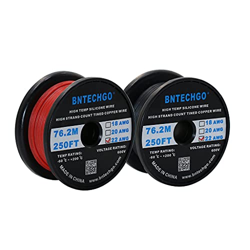
BNTECHGO 22 AWG Silicone Wire Red and Black 250 ft Stranded Tinned Copper
$46.98Enough wire and two colors for polarity for a first layout's worth of feeders and accessory connections.
Best for: Feeders, turnout motor leads, accessory wiring on a first layout
Check price on AmazonIntermediate: a terminal strip to organize a growing bus without soldering every joint
Once a layout has more than a handful of feeder drops, a terminal strip keeps the bus organized and makes changes possible without desoldering anything.

Terminal Block 8 Circuits 600V 15A Dual Row Screw Terminal Strip 6 Sets
$13.89Screw terminals let you add or move feeder connections at the bus without soldering, which matters as a layout's wiring grows.
Best for: A layout with more than a few feeder drops off the bus
Check price on AmazonExpert: extension wire for a control panel with many remote turnouts
A layout with a dozen or more remote-throw turnouts run back to a central control panel needs long, consistent leads from each switch machine, which is a different wiring job than the bus and feeders above.

Bachmann 10 foot Remote Switch Extension Wire
$17.46A ready-made 10 foot extension for a remote switch machine lead, instead of splicing scrap wire for each one on a control panel with many turnouts.
Best for: Layouts with several remote turnouts run to a central control panel
Check price on AmazonWho should not buy this tier: Skip extension wire for turnout control if your turnouts are thrown by hand at trackside. There is no control panel wiring to extend, and the standard feeder wire above covers any other short accessory runs you need.
How we chose
We did not test these products in person and we never claim to. Picks are researched from manufacturer specification sheets and instruction manuals, published NMRA standards and recommended practices, and the recurring themes in verified owner reviews. Every pick is matched to a real scale, a real minimum radius or a real current draw rather than to a price bracket, and it is placed in the tier where its capability actually belongs. Where a product is wrong for most layouts we say so on the page, and where a figure is a hobby rule of thumb rather than a published standard we say that too.
Frequently asked questions
What gauge wire do I need for my layout's bus?
It depends on your bus run length and expected current draw, since a longer run needs a heavier gauge to avoid excessive voltage drop. Use our bus wire gauge calculator with your own layout's numbers; many mid-size layouts land in the 12 to 14 AWG range for the bus itself.
Can feeder wire be thinner than bus wire?
Yes, and it usually should be. Each feeder only carries current for its own short section of rail, typically a few inches to a couple of feet, so a thin, flexible 22 AWG wire is entirely adequate even when the bus itself needs to be much heavier.
Why does a 25 foot bus run need wire sized for 50 feet?
Current has to travel out to the far end of the run and back to the source, so the effective electrical length of a 25 foot bus is 50 feet of copper. Voltage drop is calculated on that round-trip length, not the straight-line distance across the benchwork.
Do I need a terminal strip, or can I just solder every wire joint?
Soldering every joint works but makes changes difficult later. A screw-terminal strip lets you add, remove or reroute feeder connections at the bus without desoldering anything, which is useful on a layout whose wiring is still likely to change.
Why are the wires color-coded red and black?
Consistent color coding keeps polarity straightforward across dozens of connections on a layout, so you can tell at a glance which wire is which without testing every joint. It matters most as a layout grows past a handful of feeder drops.
Is silicone-insulated wire worth the extra cost over standard PVC wire?
Silicone insulation stays more flexible in cold temperatures and resists heat better near a soldering iron tip, which is convenient for feeder work done close to a hot iron. For accessory wiring away from heat, standard insulated wire performs the same job.
Researched, not professional advice. This page is compiled from published manufacturer specifications, instruction manuals, published NMRA standards and recommended practices, and owner-review consensus, not hands-on testing. Figures described as a rule of thumb are hobby convention rather than a standard, and they are labelled that way wherever they appear. Always check a radius, a clearance or a grade against your own equipment before you cut wood or lay rail, because manufacturers vary and so does what your specific models will tolerate. Any permanent mains wiring in a layout room is work for a licensed electrician to your local code.